Recently there are some discussion regarding whether ESP8266 I/Os are 5V tolerant. The most active one being the article on Hackaday. The same article was shared on ESP8266 Facebook group and Espressif CEO Mr Teo Swee Ann commented that “i can reply officially here: it is 5V tolerant at the IO. while the supply voltage is at 3.3V.“
However the Facebook post did not attract too much attentions. I went ahead and shared the same on Twitter with hashtag #ESP8266.
It’s official! #ESP8266 I/Os are 5V tolerant. #goodtoknow pic.twitter.com/SBf9a7qOx9
— Baoshi (@ba0sh1) July 30, 2016
//platform.twitter.com/widgets.js
Apparently Twitter has much more bandwidth among ESP8266 fans. Soon I received quite a few counter claims that their ESP8266s were toasted by 5V input voltage. So who is correct? The chip designer or the end users? I think it would be interesting to find out.
On a side note, Twitter user vAir (@vAirMon) pointed to me that on Page 17 of ESP8266 Datasheet it is mentioned “All digital IO pins are protected from over-voltage”. I looked into my document archive and found it does appear on “Version 4.3” of “ESP8266EX Datasheet”, released “Tuesday, May 12, 2015”.
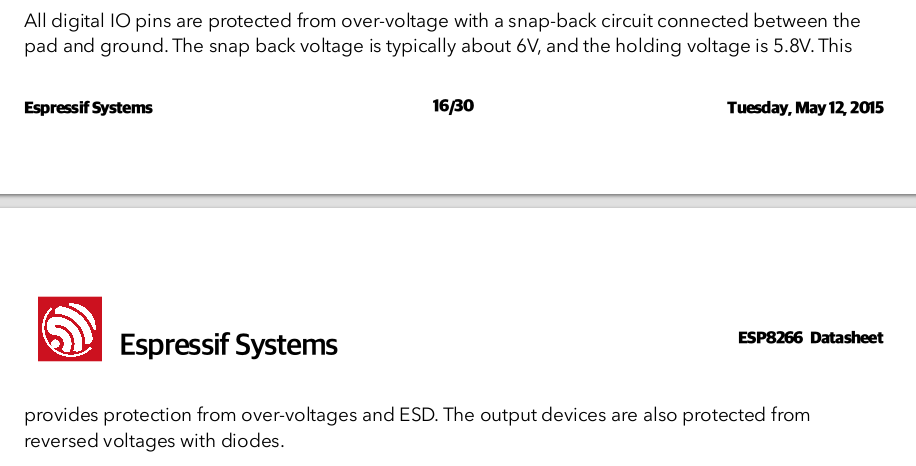
But on a more recent version, Version 1.0 (?) , released “20160422”, the whole section is removed.
Though intriguing, the “old” datasheet do point out that the over protection is based on “snap back” circuit, not the traditional two diodes voltage clamp. I found some background information of these two protection methods here. Basically snap back circuit sits only in between input and GND. There is no conductive path between input and power rail therefore it is not possible for 5V input voltage to raise the 3.3V rail.
Experiment
Assumption
The fact is that I do not have access to any die-inspection equipment. Even if I had the equipment I would not be able to tell if a silicon die was damaged from over voltage. Therefore the experiment is designed based on the assumption that I/O will only destroy the chip via excessive input or output current, which causes thermal breakdown. As the GPIOs on ESP8266 are specified to be able to source 12mA, and usually I/O pins are able to sink more current than sourcing, I conservatively assume that any input/output current larger than 12mA is able to fry the chip.
Test of over-voltage input
The experiment setup is as follows:
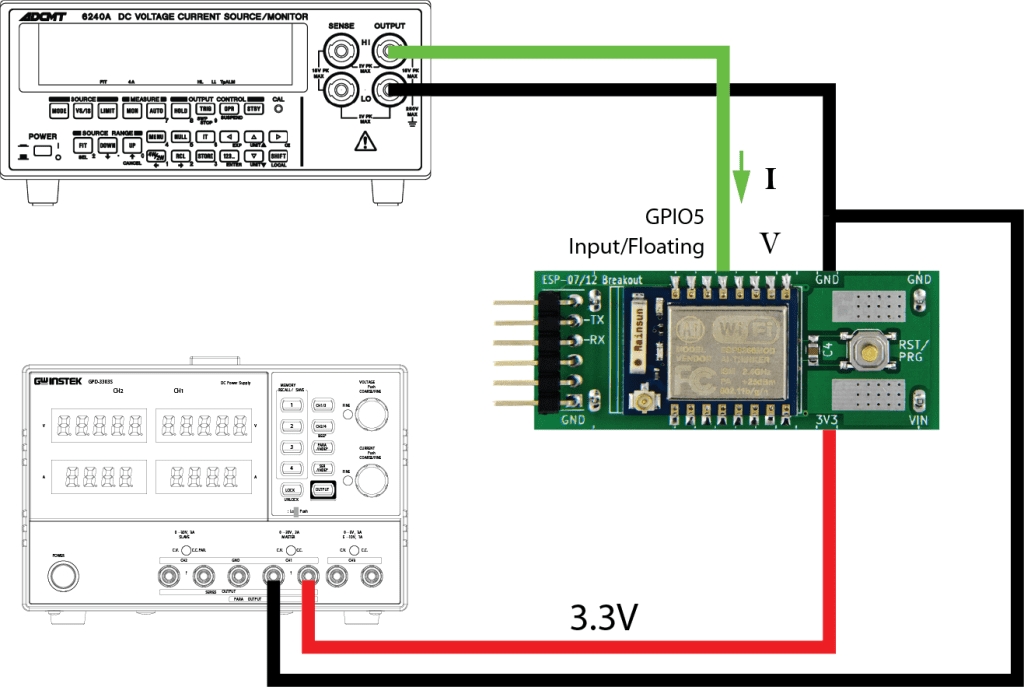
For the experiment I’m using my ESP8266 Breakout Board with ESP-12E. It has GPIO pins directly connected to the leads. The AMS1117 regulator on the breakout board is removed to get rid of LDO GND current. Instead, the module is powered with 3.3V from GW Instek GPD-3303S power supply. An Advantest/ADCMT 6240A DC Voltage Current Source/Monitor is used to simulate voltage input into GPIO5. I used the following Arduino sketch as testing firmware:
#include <esp8266wifi.h>
void setup()
{
    WiFi.forceSleepBegin(); // turn off ESP8266 RF
    delay(1); // give RF section time to shutdown
    Serial.begin(115200);
    Serial.println(F("ESP8266 in No-RF mode"));
    pinMode(5, INPUT);
    pinMode(4, OUTPUT_OPEN_DRAIN);
    digitalWrite(4, HIGH);
}

void loop()
{
    int pin5 = digitalRead(5);
    if (pin5 == HIGH)
        Serial.println(F("IN5=HIGH"));
    else
        Serial.println(F("IN5=LOW"));
    delay(500);
}
In the beginning of setup(), I purposely turned off WiFi so that the power consumption of ESP8266 can be monitored from GW Instek supply more precisely without WiFi interference.
For this experiment, I vary ADCMT 6240A power output from 0V to 5.5V in 0.1V steps. Below is the result of GPIO5 input voltage vs. input current:
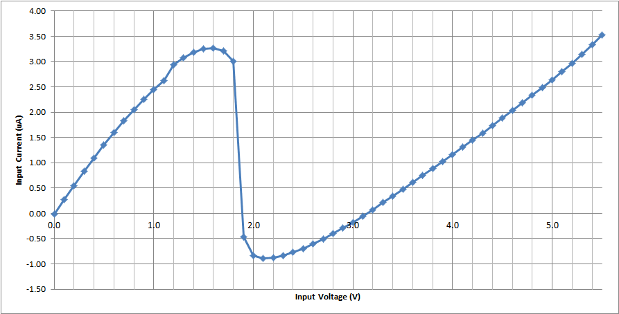
It is clear that
- When the input voltage varies from 0V – 5.5V, maximum sinking current for ESP8266 is only 3.52uA, maximum sourcing is 0.89uA
- Of all the experiment the supply current for ESP8266 stays at 16mA, GPIO input does not go into 3.3v rail.
- No any type of over current observed
- The GPIO input L-H transition is at 1.6-1.7V (not shown on the graph)
- It seems the chip internally has 1.8V and 3V domains. Some switching happens in between 1.8V to 3V where the input pin actually sources current out.
Test of over-voltage pull-up at output
Similar experiment is also done with over-voltage pull up at output pin. The setup is below:
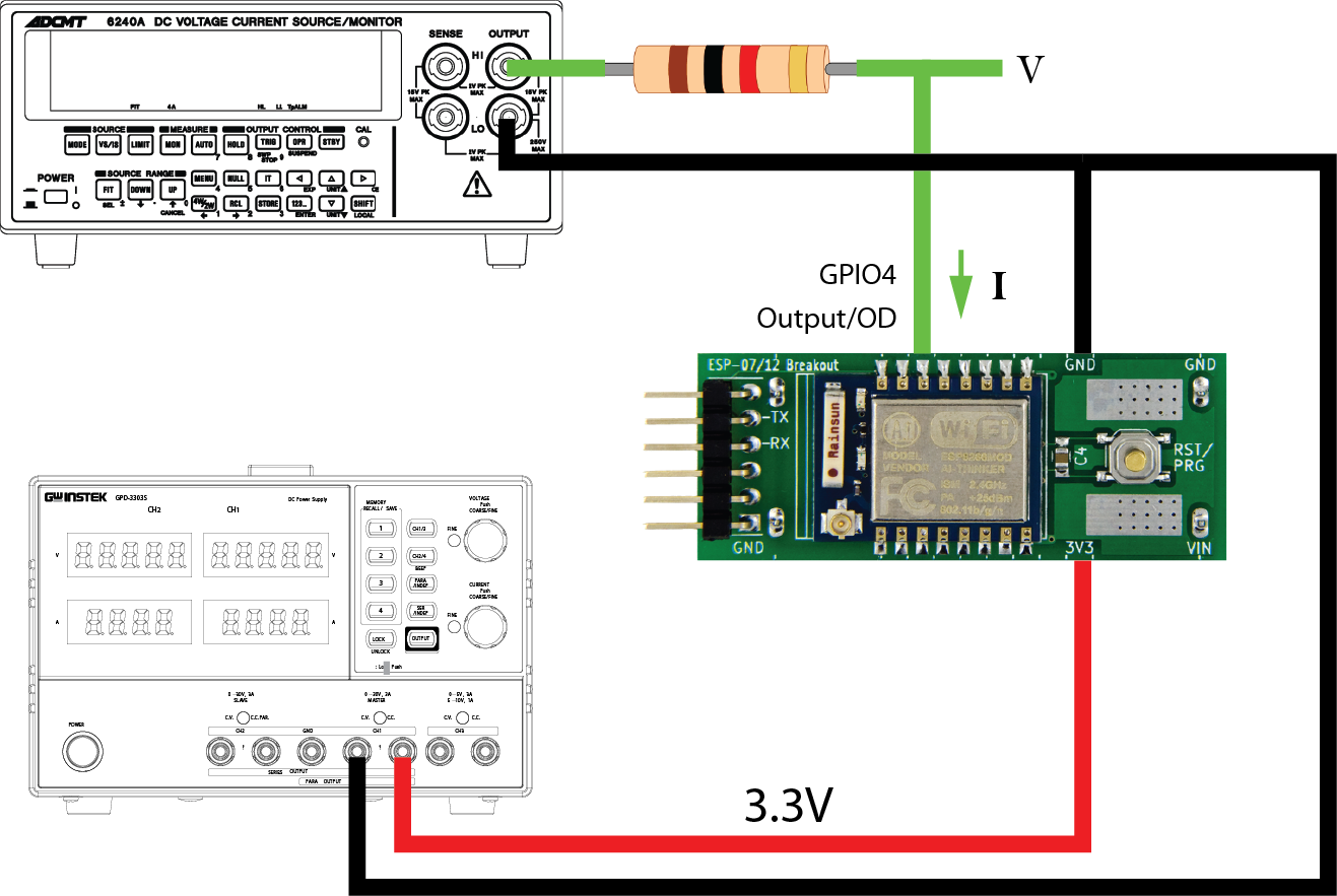
In this experiment, GPIO4 is set to Open Drain output mode. An external pull-up resistor pulls GPIO4 output above 3.3V. The choice of pull-up resistor is 1K, smaller than usually required. Because of the pull-up resistor, the current feed into GPIO4 will never go beyond 5.5mA. However it is still interesting to find out what is the actual amount.
The result is below:
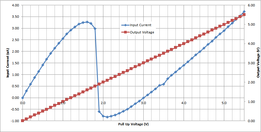
- When the pull-up voltage varies from 0V – 5.5V, maximum GPIO sinking current is only 3.72uA, maximum sourcing 0.83uA
- Of all the experiment the supply current for ESP8266 stays at 16mA
- No over current observed
- The 1.8V phenomenon can be observed too for output.
Conclusion
I believe the experiment result is conclusive. The ESP8266 I/O is 5V tolerant unless couple of uA current can destroy the chip. Except for completely wrong wiring, such as feed 5V into 3.3v rail or feed 5V into output pin (in output low state or in output high with push-pull mode), 5V on GPIO pins will not destroy ESP8266.
“5V on GPIO pins will not destroy ESP8266”
But will it operate normally with 5V inputs? I would think so but I have had weird stuff happen when driving an input above VCC.
I tried 5V UART and 5V Digital I/O, all normal. I didn’t try HSPI though. What weird stuff did you encounter?
It had to do with an A/D converter on a Microchip micro-controller. I had four load cell amplifiers going into four A/D inputs. The amplifiers were powered with 8 volts, the PIC by 5 volts. I had an RC filter after the amplifier, then that into the A/D. If any of the A/D inputs got above VCC it would shift the readings on the other A/D inputs.
I have often designed higher voltage inputs, with a series resistor, into digital inputs without problem. But the A/D experience has made me a little more cautious.
After reading this article I connected a nodemcu to a UNO via i2c without bothering with a logic convertor. I got the 8266 to send a command to the UNO, then request data from it, so that data was going both ways.
I let it run for two weeks and over 100 million packets. Not a single error or problem…
Until they update https://espressif.com/sites/default/files/documentation/esp8266_faq_en.pdf and the datasheets to say this is okay I don’t think is prudent to spread that they are 5v tolerant despite what they say and measurements confirm it. (Per August 31st the faq and datasheets contradicts 5v tolerance as far as i can tell)
Are all chips produced 5v tolerant, or only chips produced according to the “Version 4.3” of datasheet? 5v tolerance would be a significant advantage and I would think the manufacturer would announce this in more technical documentation than twitter and Facebook.
well yes, we could wait on the documentation, however I’m now just connecting all the 5v stuff to a nodemcu (after the test I did above) and everything is working fine…
and is still working fine well over a year later…
I2C worked fine here with nodeMCU 1.0 (ESP8266) as Master to Arduino Mega as Slave. (Just used a 5K pullup resistor to 3V3, just in case but it worked without it too). I would like to know if using UART serial without any level converter should work too. I found this simple circuit to make this: https://circuits4you.com/2016/12/14/io-level-conversion-esp8266/
how is it holding up? lol
They are 5V tolerant according to espressif CEO, take a look here
https://voodoo.business/2021/05/19/are-the-esp32-and-esp8266-5v-tolerant-yes-they-officially-are/
Slightly different from the IO tolerant discussion. I have a test setup where I can pulg in different development modules into a base that includes a I2C LCD and a AC power supply. I use it for the ESP8266 and also for a Arduino Nano. I have a jumper in the enclosure where I can connect the 3.3V and 5V power lines. So that the Nano gets 5 volts.
I had forgot I had that jumper in place and I plugged in one of my ESP8266 development boards. And the jumper shorted the input to the 3.3V regulator to the output. Applying 5 volts directly to the VCC line of the ESP8266.
I discovered this when I was doing some voltage measurements. I was getting 5 volts on some IO pins and I didn’t know why. In the end I discovered my error, the shorting jumper. The thing is, it worked just fine. Rand code with no problem. Didn’t burn up.
I posted this on a forum and I had a couple of people add comments. One said he always runs his ESP modules on 5 volts. He says he connects the 5V from a USB to serial adapter. He says he is too lazy to make the specified 3.3V. And he has been doing this for some time. I thought I might investigate that further some day. Part of me is in horror at the idea.
Please provide a link to the forum.
It should be very interesting to compare the same type of graphs for other platforms, such as for example the Teensy3.1.
There is a paragraph on 5V tolerance here: https://www.pjrc.com/teensy/teensy31.html
Thanks for this. Have you done similar testing on the ESP32, or would you?
i was cracking my head (and my pocket, and my watch) also.. testing with an ftdi usb serial adaptor that works smoothly, but with arduino and level conversors, dividers, etc never could get to work properly, so after thinking i “dared” to do some tests directly with 5v i/o (i have a separate 5v 1A > 3.3v s1117 voltage regulator circuit to vcc)
i still find it a little risky, so i want at least to put some serial resistor to drop voltage to 3.3v before, but that depends on gpio impedance….
q1 = does anybody know how much resistance gpio pins have? .. i can’t measure them since they send pulses and i have just a (cheap and slow) digital multimeter …. i intend to “simulate” a voltage divider, but for 5v to 3.3v to work the series resistor have to be about half of the gpio resistance value
q2 = does anybody actually knows directly which ohm value the gpio series resistor could be? … or could so some tests, find it and share with us? … thanks in advance
I tried with the ESP32 (esp32-wroom).
The ESP32 is NOT 5V tolerant, when testing a gpio pin (no pull up) with 100uA and 500uA it clamps at about 3.6…3.7V
by the way, level shifting is easy, 3V3 out to 5V input works without any modification, and for 5V out to 3V3 in use 3x1N4148 in the direction towards the input, and one schottky diode the other way, and a 10k resistor to ground.
5V out—|>|–|>|–|>|—3V3 in
|___|<|_____|
_|_
|__| 10k
|
_|_
Your results are accurate, they are 5V tolerant, an official statement from espressif makes it clear that the digital input pins are indeed 5V tolerant in sink mode.
But your research here ads confidence that it is also reliable !
What is weird is that while I was double checking that it is compatible, Google took me here, and to my surprise, I can see a post of mine has registered on this page as a pingback but using my old domain, so for anyone looking for the official statement from espressif, i made a blog post about the topic years ago.
https://voodoo.business/blog/2021/05/19/are-the-esp32-and-esp8266-5v-tolerant-yes-they-officially-are/