A small project I did while waiting for the Raspberry Pi – Arduino controlled RGB LED light.
The initial idea was stolen taken from Luminch One
I made several redesigns:
- RGB LED strip instead of original high-powered LED
- Use battery power.
The journey for battery power ends up to be much more complex. The major concern is standby (light off) power consumption. I wished the circuit could remain standby for at least one week. With three 3100mAh 18650 battery cell at 3.7V each, the maximum allowed current draw works out as 3100 * 0.8 / 7 (days) / 24 (hrs) = 14.7mA (reference here, number of cells actually does not help, but LED light needs 12V). However, the Arduino Nano alone consumes 20mA when running. After removing the power LED, it still consumes about 17mA. The distance sensor, Sharp GP2Y0A21YK0F takes another whopping 20mA. With these two monsters, standby time is 3100 * 0.8 / 37mA = 67 Hours ~ 2.8 days (show stopper).
It seems I need to turn off distance sensor and put Arduino into sleep mode during standby. It is solved by adding a Passive Infrared (PIR) sensor which powers on GP2Y0A21YK0F only when human (or pet) walks near the light. Together with AVR sleep mode the current now reduces to 2mA standby. My standby time is 51 days 🙂
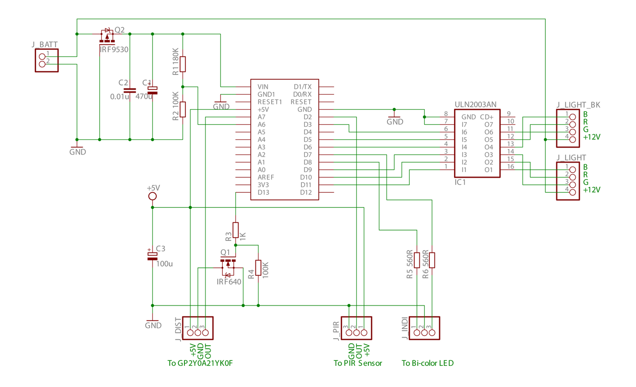
Here comes the schematic.

Notes:
- Q1 controls power to the Sharp sensor. I tried to drive this sensor directly from an Arduino pin but failed. The sensor output is unstable. I believe GP2Y0A21YK0F specified 20mA power draw is only average value. Its peak current is quite higher.
- Q2 is reverse voltage protection (reference)
- J_LIGHT is the main RGB LED light. J_LIGHT_BK is for backup.
- R1/R2 is voltage divider for battery voltage measurement.
- J_INDI connects to a Bi-color (Red/Green) LED light as indication.
The final construction will be on a perf-board. So I start Eagle PCB, set grid to 0.1inch and route the design. All files at the bottom.
Next part will include Arduino sketch, photos, and demo video. Stay tuned …
I know this is really late and I don`t know how long it will take to get a reply but here it goes… Can you explain the equation 3100 * 0.8 / 37mA = 67 Hours ~ 2.8 days (show stopper) a bit more, I don`t understand why you are multiplying by 0.8.
It is just a conservative estimation. To prolong lithium battery life I do not fully charge or discharge the battery.