During last (Chinese) year end shopping frenzy I grabbed some OLED display panels, hoping to boost the presentation of my projects. The panel model is UG-2864ASGGG14, made by “WiseChip Semiconductor Inc.” in Taiwan. Unlike typical LCD modules with complete interface board and 0.1 inch pitch pin headers, this is a bare panel comes with only the glass and flex PCB connectors.
I made an inquiry on Dangerous Prototypes forum asking for an ideas about how to make a test jig for the panel. Less than a hour later I received a replay from matseng. He suggested me to use pogopins to make a jig. And Ian also showed me a photo of test jig he bought from Shenzhen. And then started my journey to make a poorman’s version of test jig.
I defined the specification of the jig as:
- As minimalism as possible.
- Can plug into breadboard.
- Incorporate all necessary circuitries for the panel including 13V VCC supply.
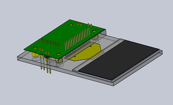
I used to jump into making stuffs without much planning, and it resulted in tons of junks under my collection. So this time I try to design everything first. Thanks to the Chinese new year holiday I had a luxury of time to spare. And here comes my final design.

With proper 3D sketching I’m able to design the PCB with precise hole positions. The schematic basically contains a DC-DC boost controller (based on LT1930, story later), some passive components and pin headers. To save space I try use surface mount components this time, hence it poses higher demand for MF70 pcb milling.

I also cut two acrylics, one for the base (left) and the other the guide (right) for solder pogo pins.

With the guide I’m able to solder the pogo pins straight.

Assemble everything together, the pogo pins seems nicely fit onto the gold contacts of the OLED panel

The panel uses SSD1305 controller. It is similar to the commonly seen SSD1306 but with some additional functions (I will update these in future blog). As for now, I simply modify on top of Adafruit’s SSD1306 Arduino library.

And IT JUST WORKS.
P.S.
About LT1930: My initial choice of DC-DC boost converter was LT1613. The reason why it was choosen is that I found a taobao.com dealer sells LT1613 at RMB2 (<$0.3) per piece. I though it was a bargain and grabbed 10 pieces from him. They come in cutting tapes like original. But And not surprisingly it does not work. I admit I only tried 2 of them but the failure rate is already 20%. After much despair I ordered some LT1930 from proper channel. Supposedly it is pin-to-pin compatible with LT1613. Finally it works. Phew!
Wow, well done. Those are some great home-made PCB and accurate hole registration skills!
And I see now from the other posts that you use a CNC to create your PCBs. Nice job!
Thanks. Yes I have to do it using a CNC. I cannot imaging how to align those holes by hand.
What Pogo pins did you use? Link please… Thanks… and Great Job!
Also those Pin headers are LONG… link please… you can email me the info if you would like.. 😀
Well I get these pins from a friend. They are made in China, model P048-J. I’m not sure if it can be purchased online. But the closest I found is http://www.aliexpress.com/store/product/100-x-P048-E-12-6MM-TWO-PART-SPRING-TEST-PROBES/703706_437319138.html (at ridiculous price). Note they are selling P048E which is sharp end. I’m using “J” type dome end. Let me know if you are interested about the pins, I see if I can help.
I bought the pin headers from a local electronics store. The length is about 19mm. The have 29mm in stock as well 😮
Cool, thanks. If possible can you email me at AtomSoft@gmail.com ? I would love to purchase some of all 3 items (Pogo, 2 different headers)
Ill be sure to include a tip 🙂 and shipping cost … Thanks for taking the time to help me out here.
Hey 🙂
can you tell me where you bought this display? I am really interested in it. Thanks
You can find it in Chinese website taobao.com, use “oled” and “2.4” as keywords. I actually have an extra new one, if you don’t mind I can sell to you at cost.
Hey Nice setup!
You said, you modified the ssd1306 library in order to run the ssd1305 display.
Could you tell me which modifications were necessary or provide the source?
I’m trying to get a ssd1305 oled running on my raspi.
Thanks in advance