Hey I’m writing my first tutorial 🙂
During my recent OLED testing I wrote the software using Arduino Pro Mini 3.3 – the only Arduino board with 3.3V I/O (Lilipad may be the other one but not breadboard friendly). Originally I was using the SPI interface and everything works fine. But when I’m trying to test the I2C interface I suddenly realize the I2C lines are not on the breadboard pins! Instead they are on top of the board and I have to use jumper wires to connect them, not as neat as I would like ;p
Looking into my inventory I found an Arduino Nano with all the necessary pins. But it uses 5V I/O only. So how to modify an Arduino Nano to 3.3V? Adafruit already has a tutorial about it. But judging from the photos the modification is on a Uno. Uno uses different USB chip from Nano’s FT232RL, and hence we need some more steps.
So here is what we need:
- Arduino Nano (of course)
- A 3.3V regulator in SOT-223 package. Please note the official Nano design uses UA78M05 regulator, which has a different pin configuration than the popular LM1117-3.3. The one I found compatible is Micrel’s MIC37100-3.3WS, Digikey link here.
- An Atmel ISP programmer, such as AVR JTAGICE mkII, or usbasp, or even a second Arduino as ISP.
- A good magnifier!
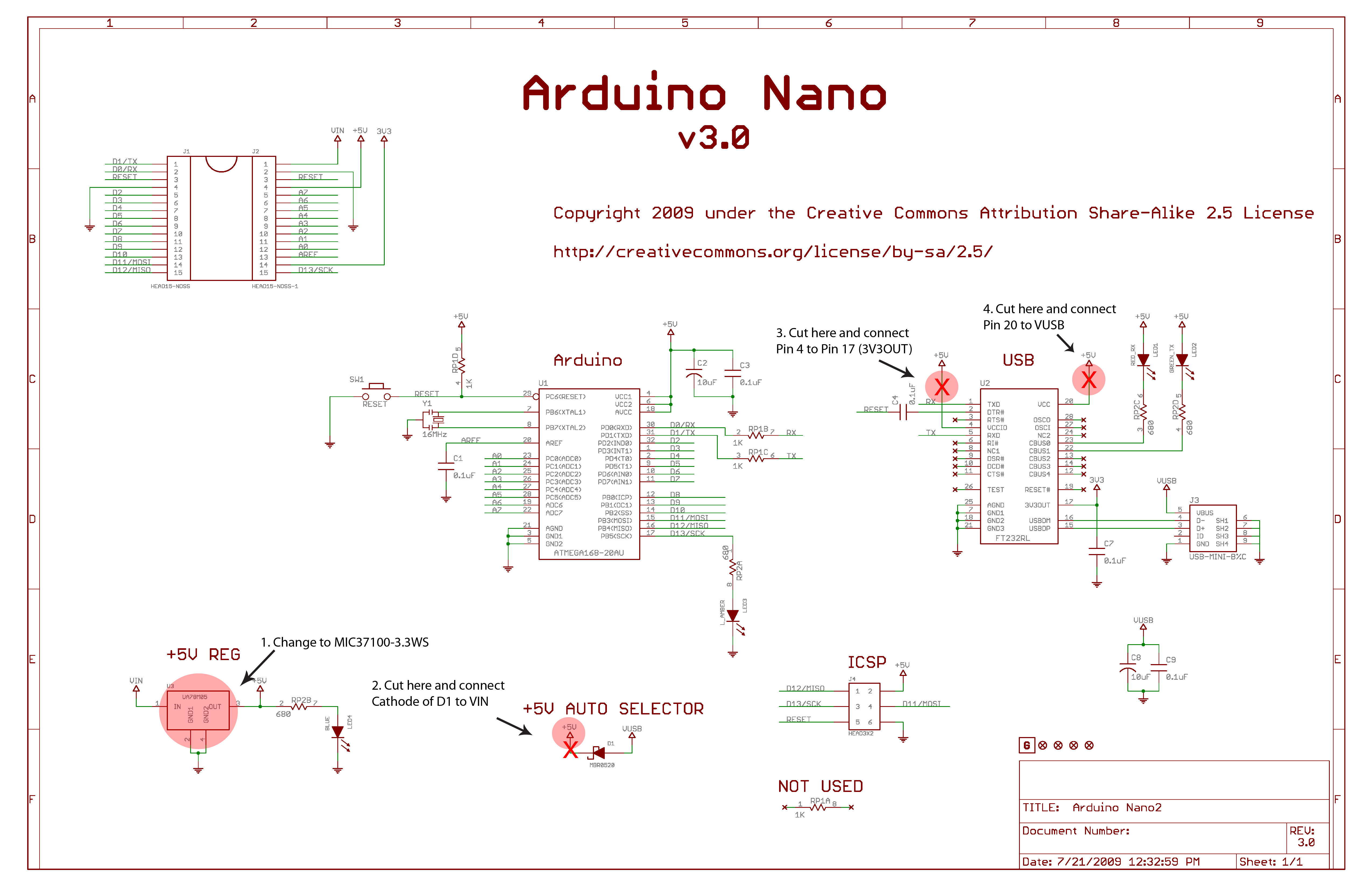
Schematic below is the official Arduino Nano design with necessary modifications marked in red:

- Replace the original voltage regulator.
- Locate D1 from the board, cut the trace at cathode side and connect cathode to VIN of the regulator. Alternatively you can also remove D1 completely, but by doing so the Nano board is unable to be powered from USB, You’ll need to provide your own source voltage from Pin 1.
- Cut the trace at FT232RL pin 4 (VCCIO), and connect pin 4 to pin 17 (3V3OUT). This enables FT232RL to use 3.3V logic.
- Cut the trace at FT232RL pin 20 (VCC) and connect pin 20 to D1 anode (VUSB).
I would suggest to trace your board carefully before doing step 3 and 4. In my case the board is a Chinese enhanced modified version and all the power pins are connected by vias under FT232RL. So I had to desolder the whole chip to break the links. Just to share my modified board:

Till here the hardware modification is done.
However, if you carefully read the 660-page ATmega328 datasheet (which you should), at the bottom of first page:

Yes the chip is only specified at 10MHz with 3.3V supply. So unless you want to overclock your 3.3V Arduino at 16MHz, you should try to reduce the clock frequency.
Although the simplest way to modify clock frequency is to replace the 16MHz crystal with a 8MHz one, I’m out of luck because my board is using a tiny resonate instead of standard HC-49S crystal.
So the other way is modify the Arduino bootloader, configure CLKPR register to divide the clock by 2. To do this, follow the steps below:
- Go to “c:arduino-1.0.3hardwarearduinobootloaders”, make a copy of “atmega” folder, I name my new folder “atmegad2”
- Inside “atmegad2”, edit “ATmegaBOOT_168.c”, look for the main() function and add the following
[code language=”cpp”]
uint16_t w;#ifdef CLKDIV2
// Disable interrupts
ch = SREG;
cli();
// Enable clock change
CLKPR = _BV(CLKPCE);
// Change clock division
CLKPR = 0x1;
// Enough time for new clock to be stable?
asm volatile(
"nop nt"
"nop nt"
"nop nt"
"nop nt"
);
SREG = ch;
#endif#ifdef WATCHDOG_MODS
…
[/code] - Edit “Makefile”, add a new build target (I added right below “atmega328_pro8_isp: isp”)
[code]
atmega328_pro16div2: TARGET = atmega328_pro_16MHz_Div2
atmega328_pro16div2: MCU_TARGET = atmega328p
atmega328_pro16div2: CFLAGS += ‘-DMAX_TIME_COUNT=F_CPU>>4’ ‘-DNUM_LED_FLASHES=1’ -DBAUD_RATE=57600 -DDOUBLE_SPEED -DCLKDIV2
atmega328_pro16div2: AVR_FREQ = 8000000L
atmega328_pro16div2: LDSECTION = –section-start=.text=0x7800
atmega328_pro16div2: $(PROGRAM)_atmega328_pro_16MHzDiv2.hex
[/code] - Create a batch file “env.bat”, content below. This is to set correct building environment for the boot loader. You do not need a separate installation of WinAVR as the current version of WinAVR has some definition problem with Arduino bootloader source. The WinAVR within Arduino distribution is just fine.
[code]
set path=c:arduino-1.0.3hardwaretoolsavrbin;c:Appsarduino-1.0.3hardwaretoolsavrutilsbin;%PATH%
[/code] - Open a command prompt, cd into “c:arduino-1.0.3hardwarearduinobootloadersatmegad2”, execute the follow:
[code]
c:arduino-1.0.3hardwarearduinobootloadersatmegad2>env.bat
……..
c:arduino-1.0.3hardwarearduinobootloadersatmegad2>make atmega328_pro16div2
avr-gcc -g -Wall -O2 -mmcu=atmega328p -DF_CPU=8000000L ‘-DMAX_TIME_COUNT=F_CPU>>4’ ‘-DNUM_LED_FLASHES=1’ -DBAUD_RATE=57600 -DDOUBLE_SPEED -DCLKDIV2 -c -o ATmegaBOOT_168.o ATmegaBOOT_168.c
avr-gcc -g -Wall -O2 -mmcu=atmega328p -DF_CPU=8000000L ‘-DMAX_TIME_COUNT=F_CPU>>4’ ‘-DNUM_LED_FLASHES=1’ -DBAUD_RATE=57600 -DDOUBLE_SPEED -DCLKDIV2 -Wl,–section-start=.text=0x7800 -o ATmegaBOOT_168_atmega328_pro_16MHzDiv2.elf ATmegaBOOT_168.o
avr-objcopy -j .text -j .data -O ihex ATmegaBOOT_168_atmega328_pro_16MHzDiv2.elf ATmegaBOOT_168_atmega328_pro_16MHzDiv2.hex
rm ATmegaBOOT_168_atmega328_pro_16MHzDiv2.elf ATmegaBOOT_168.oc:arduino-1.0.3hardwarearduinobootloadersatmegad2>
[/code]When the building ended, you should have “ATmegaBOOT_168_atmega328_pro_16MHzDiv2.hex” in the folder.
- Use you ISP programmer, burn “ATmegaBOOT_168_atmega328_pro_16MHzDiv2.hex” into ATmega328p chip. You do not need to reprogram the fuses but just in case you need, the fuse settings are:
[code]
HFUSE = DA
LFUSE = FF
EFUSE = 05
[/code]
Now you can use your Arduino Nano just as an Arduino Pro Mini 3.3/8Mhz, write some blink LED program to test the new clock. Have fun with 3.3V devices!
Hello, I link your website on mine, very nice stuff. bye
hi thanks for this tuto !
just a question, why do you change the ftdi vccio connection ? In original nano it’s connected to “+5V” bus, which became actually a 3,3V by changing the regulator, so no need to change it ? am i wrong ?
Matthieu
If VCCIO is +5V, the RX/TX of FT232 will become 5V as well. I’m not sure if ATMega328p’s RX/TX is 5V tolerant when it is running at 3.3V. So I choose to stay at safer side and use 3.3V I/O.
Sorry, i was not clear enough…
if you change the regulator, it will change all the supply lines, there will be no 5V anymore, nowhere, am i wrong ?
The so-called +5V will become ACTUALLY a +3,3V one !
5v is required for FT233RL when internal oscillator is used. So I have to move FT232 power supply to VUSB
There is no need to change the Arduino nano to obtain +3.3V levels on the I2C signals.
If you have both 5V and 3.3V I2C busses a level translator can be used.
For a single signal the level translator consists of a MOSFET, such as a BSS138. SOurce to the low level side, drain to the high level side, gate on +3.3V. The best results can be obtained if the transistor is bridged by a schottky diode (e.g. BAT54), drain to cathode, source to anode.
Both sides should have a pull-up resistor, the drain to +5V, the source to +3.3V. The two resistors should not present a load above 3mA! If these resistors are called Rs(ource) and Rd(rain) then 5V/Rd + 3.3V/Rs <=3mA.
This because I2C chips cannot sink more than 3mA.
So in essence you need 2xBS138, 2xBAT54 and two extra resistors and you have your 3.3V I2C interface without any modifications to the Arduino.
Regards,
Brody
“the chip is only specified at 10MHz with 3.3V supply” No that is not true! Only at 2,7V you Need to choose 10MHz. Actually the 328P can be driven with 13.3MHz at 3.3V. More common is a 12MHz crystal, which you can get everywhere. Take a look at page 303 in the datasheet.
I found no issues so far using the atmega328 with 2.8 – 3.3V at full 16MHz. In Fact, it is the only reliable way to overclock it to 25MHz without any major temperature increase (At 5V it gets pretty hot/unstable)
At 2.7V the internal watchdog resets the micro, the most common cause for CPU erratic operation, if the supply is not properly decoupled. So if the project is not some crytical application, 3.3V works reasonably well between 12-16MHz.
I am powering my Nano V3 Clone (CH340G USB/serial) with 4.2V on Vin. Then the buildin regulator gives 3.3V to the AVR and it can also drive 3.3V modules on the 5V-Pin (a.k.a. 3.3V). The clock is at 16MHz. The downside is that I can not use the USB/serial at the same time.
Other good alternatives for the regulator, which are half the price (in the UK at least), are the MicroChip MCP1825S-3302E, or TC1262-3.3VDB
Very nice tutorial. I alays wondered why nobody produced a 3V3 Nano!
To some commenters, the idea here is to make all I/Os (and also VRef/ADCs etc) work at 3V3, even if there is some Vin or VUSB present ! That can’t be done without HW modifications.
FYI, overclocking at 16MHz has been done by JeeLabs for years without any report of problems.
Note also that MCP regulators only accepts voltages up to 6V. That’s OK for USB, but the nano original specs states that Vin can accept 7V to 12V (or even 6V to 20V).