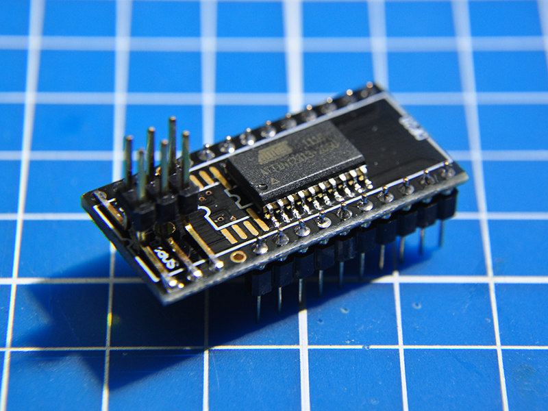
The AVR chip I’m talking about is Atmel ATTiny2313, in SOIC-20 package. To make the development board, I bought some 28 pin SOIC/SSOP to DIP adapters. These adaptors usually come in double sided design. Corresponding pins on both sides are connected via the plated through holes at edges.

I made a 2×3 AVR programming header by pulling off pins (longer ones) from a double-row right angle pin header and reinsert them into the plastic base. A needle nose pliers is very handy for this purpose.

Both the programming header and the chip are soldered onto the SOIC side of the adaptor board. The programming header is taking pin 1-3 and 26-28. ATtiny2313 is taking pin 5-14 and 15-24 (numbering according to adaptor board).

Since the corresponding pads at both sides are electrically connect, it is easy to wire the programming header from the back side or the adapter, using enamel wires and some kapton tape. These pads are 0.5mm pitch so a really fine solder tip is necessary (I use Metcal STTC-126).

Finally install the pins for breadboarding, a minimalism AVR development board is ready to roll. (Picture of ATTiny2313 and ATTiny85 boards below).


Nice work!
Looks like you could use the pads above pin1 and pin20 of the 2313 to solder a 0805 .1uf decoupling cap. Then you could easily wire those to Vcc & Gnd.
Good idea! Saves two hole on the breadboard too.