The rise of the ESP8266 WiFi chip was almost overnight with Espressif’s open approach and pushing from Hackaday. While no ground-breaking product has yet emerged, the development on the chip are phenomenon. However due to an unknown reason the ESP8266 modules manufacture seems to prefer non-standard 2.0mm pitch connector, which gives a lot of headache to breadboarding lovers like me. This forced me to make a breadboard friendly ESP8266 breakout board.
The modules I’m targeting are ESP-07 and ESP-12, both having identical pinout but only differ in antenna type. I choose these two because they have all the I/O available, and using same edge castellation (half vias) connectors which is easy to work with.

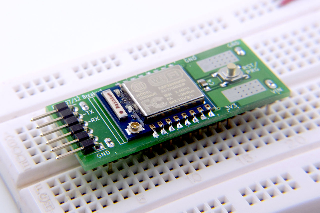
The modules are 16mm tall, easily occupies 4 rows (2 rows on each side) on a breadboard. Therefore my first design requirement is to minimize real estate on the breadboard. To do this I made some custom pin headers by modifying from SMT pin header.

I removed pair of pins from both ends and replace with through hole pins. This little touch strengthens the bounding between pin header and the board. If otherwise on my first version I can easily pull up all the pads when lifting the board up from breadboard. With this design, I maintain 4 rows occupation on the breadboard, that leaves another 6 rows for wiring.

The boot mode of ESP-8266 is often another source of confusion. The table below summarizes different boot modes during power on or reset:
| Boot Mode | CH_PD | GPIO15 | GPIO0 |
| Run firmware | High | Low | HiZ (Internal P-UP) |
| Flash firmware | High | Low | Low |
In firmware flashing mode, user is able to update new firmware from UART0 using FLASH_DOWNLOAD_TOOLS or esptool.py.
The board is designed for ESP8266 developers so reset and flash must be made easily accessible. I designed a simple circuit that only uses one button to perform these two tasks:

During idle state, internal pull-up in the ESP8266 RESET pin turns on Q1. Q2 cut off so GPIO0 remains high due to GPIO0 internal pull-up. At the same time, C1 discharges from R2 and Q1. When user presses SW1, RESET goes low immediately. Meanwhile, Q1 turns off and 3.3V power charges C1 through R1 and R2. If user releases SW1 quickly and the voltage across C1 has not reached Q2’s threshold voltage, Q2 remains off and ESP8266 enters normal running mode. However if user holds SW1 long enough before releasing, Q2 will turn on, pull GPIO0 low. At the moment user releases SW1, RESET goes high but GPIO0 will be held low for a while due to C1 have to discharge through R2 and Q1. The choice of C1 and R2 are such that it keeps GPIO0 low long enough for ESP8266 to enter program mode.
The board also includes a 3.3V LDO (AMS-1117 3.3) and a UART header using FTDI Basic pin out. Below is my programming hardware. (Yes I’m writing OLED driver, which will be release right after).

The schematic and board are designed using KiCad BZR 5312. Windows binary is available at http://kicad.nosoftware.cz/. I have uploaded the schematic and PCB onto my GitHub page at
https://github.com/baoshi/ESP-Breakout
At the moment I’m trying to sell extra boards on Tindie. Please visit my store

Product link -> https://www.tindie.com/products/Ba0sh1/esp8266-esp-0712-full-io-breadboard-adapter/
This is my first attempt to generate some income via hobbyist project. Please support if you also want to join the ESP8266 fun!
Thanks
how’s that OLED coming? I’ve got some i2c Oleds – thinking it would be perfect for displaying weather info, etc.
Hi, it’s here. https://github.com/baoshi/ESP-I2C-OLED
what 8266 firmware and what tools do you use with this?
Have to write own firmware. Using the Espressif rtos sdk and they supplied toolchain in a Lubuntu VM. You can found the tools on http://bbs.espressif.com/viewforum.php?f=21 and discussion on esp8266.com
I just recieve my modules for me and my friends. Thank you very much.
Thanks for kind patronage.
Where Can I find yours kicad libraires for AMS1117 ? In general wich librairies do you use ?
It is the LD1117S33TR in “regul” schematic library.
And thank you too for kicad librairies, i can reuse it for my projects.
Nice post , but the table has error. To flash the chip PIO has to be low , and in the table you write High
Can we chat over Skype ? nissim.test
-Nissim
Thanks! Have corrected in the post. Probably had misled many people, sorry!
Is GPIO15 (ESP8266 pin 13 MTDO) really needed to hook to GND… ?
Can you explain way not to let it float ?
I like to hire you to some small programming work, can you call my Skype nissim.test
Thank you
-Nissim
Hi, great board 🙂 can you tell me the sw1 part number?
The closest part is http://www.cnbbj.com/inc/products_viewEn.asp?id=89
I’m not sure if DigiKey or Mouser have them but if you type “tact swtich copper head 4×4” into google they are everywhere,.
Thank you,
Yours have a very high switch and that is something that I can’t find on mouser for such low profile body.
Yes they come in various heights. The very flat one is hard to press.
I see low stock on tindie when will you have more,. Looking for 5 with ESP 07
New PCBs in the making. Will have stock before the end of next week.
Hi Baoshi,
Nice write up 😉
Just one question about autoreset/flash you made (very nice trick by the way) do you think it could work if we connect DTR from FTDI adapter to reset line ? Technically it should works not ? May be C and R values need to be adjusted for correct timing depending on how DTR is pulled low.
Worth it testing 😉
Hi Charly,
I’m think it can work. But looks like we need to modify esptool.py to toggle DTR with correct timing, and this breaks other flash programs that we do not have source code. I’m currently making another board which fully automates the programming. Will release once its ready.
Cheers 🙂
Thanks for a great board. Is there any chance you could update the repo with the latest v1.1 design files please?
Done. Please use latest nightly build KiCad to open.
Great Project, Thanks!
I have made some PCB and the only thing i miss are some LEDs onboard.