Skip to content

Digital Me

Electronics, Computers at leisure time

Menu
  • Home
  • Contact
  • About
Menu
Minimalism ATTiny2313 development board

Minimalism AVR development board

Posted on October 15, 2014
Lacking of proper development board always poses huge resistance for me to jump onto a new MCU. Even with the most prototyping friendly DIP packages, wiring a programming header onto the breadboard is both troublesome and unreliable. Things become worse when the MCU is an AVR. There is absolutely no way to mount a 2×3 0.1in pitch programming header onto the breadboard. It was such a pain until recently I found a elegant way to make a quick and dirty minimalism board. Here is how.

The AVR chip I’m talking about is Atmel ATTiny2313, in SOIC-20 package. To make the development board, I bought some 28 pin SOIC/SSOP to DIP adapters. These adaptors usually come in double sided design. Corresponding pins on both sides are connected via the plated through holes at edges.

SOIC/SSOP - DIP adaptor
SOIC/SSOP – DIP adaptor

I made a 2×3 AVR programming header by pulling off pins (longer ones) from a double-row right angle pin header and reinsert them into the plastic base. A needle nose pliers is very handy for this purpose.

AVR programming header

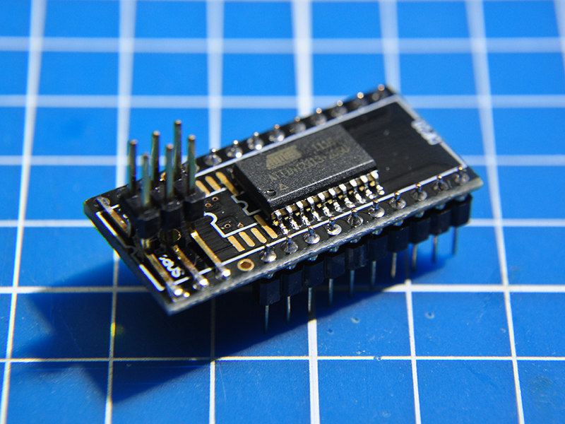
Both the programming header and the chip are soldered onto the SOIC side of the adaptor board. The programming header is taking pin 1-3 and 26-28. ATtiny2313 is taking pin 5-14 and 15-24 (numbering according to adaptor board).

Front side of AVR development board

Since the corresponding pads at both sides are electrically connect, it is easy to wire the programming header from the back side or the adapter, using enamel wires and some kapton tape. These pads are 0.5mm pitch so a really fine solder tip is necessary (I use Metcal STTC-126).

Back side of AVR development board

Finally install the pins for breadboarding, a minimalism AVR development board is ready to roll. (Picture of ATTiny2313 and ATTiny85 boards below).

Minimalism ATTiny2313 development board


3 thoughts on “Minimalism AVR development board”

  1. Ralph Doncaster says:
    October 16, 2014 at 7:52 am

    Nice work!
    Looks like you could use the pads above pin1 and pin20 of the 2313 to solder a 0805 .1uf decoupling cap. Then you could easily wire those to Vcc & Gnd.

    Reply
    1. Baoshi says:
      October 16, 2014 at 8:29 am

      Good idea! Saves two hole on the breadboard too.

      Reply
  2. Pingback: Minimalism AVR development board | Tehnik Service

Leave a Reply Cancel reply

Your email address will not be published. Required fields are marked *

Arduino ARM AVR Charger CNC Distance Sensor emWin ESP31 ESP32 ESP8266 FT230X GCC iPad JTAG LED Strip Makefile Maker Faire MF70 OLED Oscilloscope PCB PIR Sensor Pogo pin PWM Raspberry Pi RGB LED Rigol RTOS Saleae SEGGER Shopping SPI SSD1305 SSD1306 STM8 STM32 STM32Cube STM32CubeMX Storage TFT Tindie Tool USB Power VFD Workbench

Recent Posts

  • Arduino Redesigned – Maker UNO Review
  • Is ESP8266 I/O really 5V tolerant?
  • First sight into ESP32
  • ESP8266 MQTT client on RTOS
  • Maker Faire, Yearly Review, and Rant

Archives

  • March 2018
  • August 2016
  • December 2015
  • August 2015
  • July 2015
  • April 2015
  • February 2015
  • January 2015
  • December 2014
  • October 2014
  • July 2014
  • May 2014
  • March 2014
  • January 2014
  • December 2013
  • November 2013
  • August 2013
  • July 2013
  • May 2013
  • March 2013
  • January 2013
  • December 2012
  • November 2012
  • October 2012
  • September 2012
  • August 2012
  • July 2012
  • June 2012
  • May 2012

Meta

  • Log in
  • Entries feed
  • Comments feed
  • WordPress.org
©2023 Digital Me | Design: Newspaperly WordPress Theme